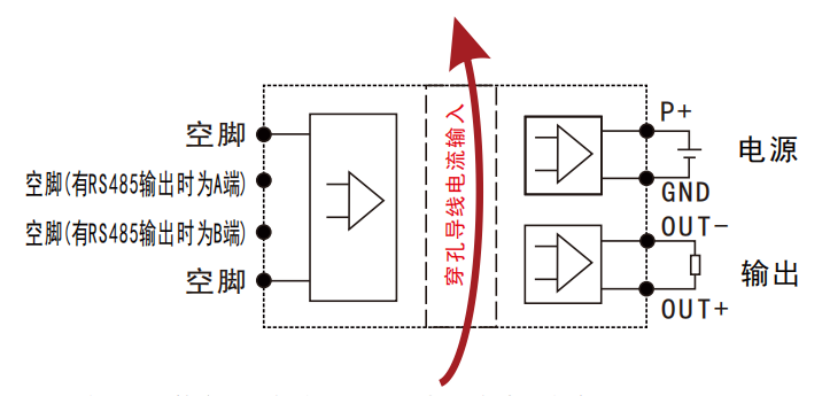
AC/DC Current & Voltage Sensor
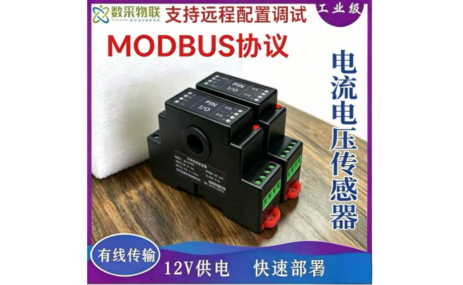
The DAQ-GP-A/DCT/VT series AC/DC current and voltage sensors are one-in-one-out industrial-grade signal transmitters produced by Shanghai DAQ IoT Technology Co., Ltd., used for real-time measurement of current and voltage in AC/DC…
Get a QuoteProduct Details
1 Product Overview
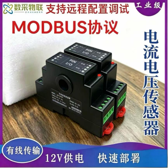
The DAQ-GP-A/DCT/VT series AC/DC current and voltage sensors are one-in-one-out industrial-grade signal transmitters produced by Shanghai DAQ IoT Technology Co., Ltd., used for real-time measurement of current and voltage in AC/DC circuits. The product uses high-precision ultra-microcrystalline iron-core coils and industrial-grade chips, with true RMS measurement, featuring high accuracy, good stability and strong anti-interference capability. It can convert AC/DC electrical parameters into standard analog outputs such as DC420mA, DC05V, DC0~10V, or RS485 digital output, compatible with various PLCs, touch screens, DCS and industrial acquisition devices. It is widely used in electric power, communications, environmental protection, computer room monitoring, industrial measurement, distribution monitoring and other fields.
3 Functional Features
-
Supports three input modes: through-hole current input, terminal current input and terminal voltage input
-
True RMS measurement with high accuracy, good linearity and low temperature drift
-
Three-terminal electrical isolation of input/output/power supply, strong anti-interference
-
Wide-range AC/DC power supply, adapting to various on-site power sources
-
Standard 35mm DIN-rail mounting, easy to install and simple to maintain
-
Optional outputs: DC4
20mA, 020mA, 05V, 010V, RS485 -
Industrial-grade wide-temperature design, stable and reliable over the long term
-
Supports customization of input range, output signal and supply voltage
-
Strong overload capacity, meeting harsh industrial on-site environments
4 Main Technical Parameters
| Parameter | Specification |
|---|---|
| Input type | Through-hole current input (within 150A); terminal current input (within 20A); terminal voltage input (within 1500V) |
| Input range | A/DC 0 |
| Output signal | DC4 |
| Accuracy class | 0.2% F.S |
| Response time | ≤200mS |
| Isolation withstand voltage | 3KV/50Hz, 2mA, 1Min |
| Temperature drift | 0.02% F.S./℃ |
| Bandwidth | 40~5000Hz |
| Load capacity | 500Ω (DC4 |
| Rated power consumption | 0.7W (4 |
| Overload capacity | 2× nominal input for 1s; 10× nominal input (through-hole type) for 10s |
| Operating temperature | -20℃~80℃ |
| Storage temperature | -25℃~85℃ |
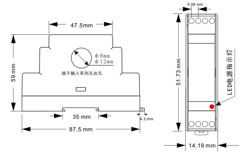
| Installation | 35mm standard DIN-rail mounting |
| Through-hole diameter | φ8mm, φ12mm (T4I only) |
| Power supply | DC24V/DC12V/±12V/±15V; AC85 |
5 Interface Description & Installation
5.1 Terminal Definition
-
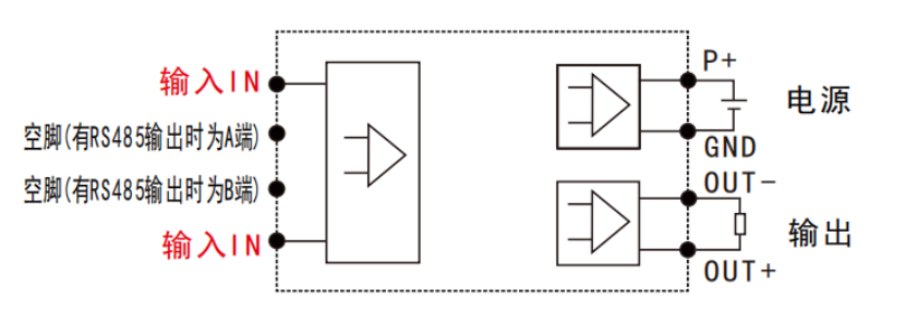
P+: power positive
-
GND: power negative / common ground
-
OUT+/OUT-: analog output positive/negative
-
A: RS485A (RS485 models only)
-
B: RS485B (RS485 models only)
-
NC: no connection, leave floating
5.2 Wiring Notes
-
Terminal input: connect the measured AC/DC voltage/current to both ends of IN
-
Through-hole input: pass the measured cable directly through the center hole of the transmitter
-
RS485 communication: the A and B wires must never be reversed, and addresses of multiple devices connected in parallel must not conflict
-
The NC pin must always be left floating and never connected
5.3 Installation
-
Standard 35mm DIN-rail clip mounting
-
Installation environment: no strong corrosion, no severe vibration, good ventilation
-
For the through-hole type, keep the cable straight and avoid squeezing or bending
6 Outline Dimension Drawing
7 Wiring Diagrams
7.1 AC/DC Voltage Terminal Input Wiring Diagram
7.2 AC/DC Current Through-Hole Input Wiring Diagram