Edge Computing Gateway Communcation Management Machine
1****Product Overview
1.1****Functional Overview
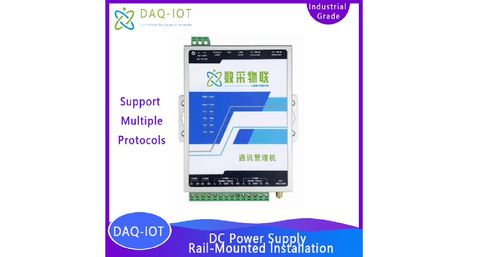
Communication management machine, support 9~48 V DC DC power supply, guide rail installation. The hardware configuration is as follows:
4 -way RS 485 interface , 2 RJ45 Network port, 1 way 4G or WiFi interface.
Communication management machine, support 9~48 V DC DC power supply, guide rail installation. The hardware configuration is as follows:
16 road RS 485 /RS232 Interface ( multiplexing ) , 4 indivual RJ45 Network port, 1 way 4G or WiFi interface.
CAN interface and DI/DO interface are optional.
****Overview of built-in software
built-in DAQ for IIOT The general industrial data acquisition system is a set of data collected by edge computers, industrial gateways or general Equipment data acquisition management software on the computer, mainly used for various industrial instruments and equipment, PLC , injection molding machines, CNC machine tools The collection, control, storage, statistics and upload of other data.
********Operating Environment
| project | Require |
|---|---|
| operating system | Windows, Linux |
| Software Basic Environment | .NET5 |
| Client browser | Edge, Chrome, Firefox, Safari, Opera, etc. |
********Supported devices
The data acquisition system collects data by connecting to the device. The supported connection methods include serial port ( 232 , 485 ), TCP Client, TCP Server, UDP Etc. The data acquisition system supports a wide range of device communication protocols, including Modbus , OPC - UA wait.
********Glossary
The software collects data from a device that has a communication interface and uses a specific communication protocol to communicate. The device can be a detection instrument, a small meter, a sensor , or even a separate PLC .
Factors are the properties of a device, including its measured value, state, control unit, etc. For example, for an air conditioner , The following attributes can be called a factor:
The physical connection method between the data acquisition system and the equipment and the basic communication protocol. For example, it can be using a serial communication line, using RS 232 or RS 485 interface; or use network cable RJ 45 interface, use TCP / IP Communication protocol. Support multiple devices
Share a link.
The communication protocol analysis program between the data acquisition system and the device. On the one hand, it analyzes the data collected from the device into the data format used by the acquisition system, and on the other hand, it analyzes the commands sent by the acquisition system to the device into the data format understood by the device. Mode.
********Usage Process
The software usage process is shown in the figure below:
1 ) The software must first be installed and authenticated.
2 ) Before data collection, the system needs to be configured.
3 ) After the configuration is completed, it will enter daily use, generally starting and stopping monitoring and collection.
********Service Concept
Our company solemnly promises:
You buy not only the product, but also the meticulous and thoughtful technical support service ! ! ! ( =^_^= )
This product only needs ordinary workers to connect the power and install it on site! No debugging is required!
We provide free remote guidance, remote configuration and debugging services, and send data to the user’s designated cloud platform.
Free IoT solution consulting services!
********Software Installation and Authentication
********Software Installation
Before software installation , make sure that .NET 5 Runtime Successfully installed . Microsoft Official Website Download and install ( https://download.visualstudio.microsoft.com/download/pr/f92c52da-2ef 6-44f2 - a296-487f94c2c 37a/258 dc 2e61 ff 8 bec 7d90 aee 3 ca 1e7d8a3/ dotnet - sdk - 5.0.406- win - x64.exe ).
exist Windows On the system, after downloading the installation package, run the installation program , as shown below:
Select the installation directory, agree to the user license agreement, and click the Start Installation button to complete the software installation.
********Open the management page
After the software is installed, it will start running in the background. If you need to perform configuration, management, authentication, etc., you need to open Open the Software Management page.
Use a modern browser (recommended Edge or Chrome ), type http :// localhost :28901/ , you can access the management The page is as shown below:
********Software Certification
The software needs to be authenticated before it can be used normally (otherwise the software cannot collect data). The authentication operation is completed on the software’s About page:
The certification process is:
1. Copy the machine code and provide it to the supplier.
2. Obtain certification documents from suppliers.
3. Upload the certification documents.
It should be noted that one authentication file can only authenticate one computer.
********Collection Configuration
********Driver Management
The driver management page is shown in the figure below:
You can download the driver of the corresponding device from the official website, upload it to the system, and then use it for the device.
********Link Configuration
The link configuration page is shown below:
The currently supported links and the contents that need to be configured are shown in the following table:
| Link Type | Contents to be configured | Remark |
|---|---|---|
| TCP Client | server IP ,port | |
| Serial Port | Serial port number, baud rate, check bit, data bit, Stop bits | |
| TCP Server | server IP ,port | |
| UDP | remote IP , port, local IP ,port | |
| OPC - UA Client | server URL , Username, Password | Only anonymous and username login methods are supported If the user is empty, it is anonymous. |
| No transmission | none | For virtual devices |
****Equipment Configuration
The device configuration page is shown below:
Devices using different drivers will have different configuration information. However, some information needs to be configured for all devices, such as
| Configuration Content | illustrate |
|---|---|
| Using the driver | The driver used by the device. You can select the driver added in the driver management page. |
| Use Link | The link used by the device. The link added in the link configuration page is optional. |
| Send waiting time | The frequency at which the system sends commands to the device when collecting data. The unit is milliseconds. |
| Receiving waiting time | After the system sends a command to the device, the expected time for the device to respond normally. The unit is milliseconds. |
| Stop collecting errors number | In a transmit - receive loop, if an error occurs, the error count is incremented. 1 When the number of errors exceeds this value, Wait for a while before starting the collection. |
| Stop collection time | The time to stop collecting data after the number of errors exceeds the limit, in milliseconds. |
The following table shows:
The device contains factors, and the factor configuration page is shown below:
Similarly, for devices using different drivers, the information that needs to be configured for the factors is also different. The two common attributes are as follows: Down:
********expression
If the value you want to display / upload is different from the original value collected from the device, you can use an expression to match it. For example, the unit of the collected data is mg , but the unit of uploaded data is g , then you need to divide the original value by 1000 The expression supports basic operations, including four arithmetic operations, exponential operations, trigonometric functions, etc. For operation support, please refer to Section A1 .
A reference to itself in an expression is { self } , references to other factors are { device name . Factor Name } , For example :
| occasion | Existence Factor | Expression Writing |
|---|---|---|
| The original unit is mg , need to upload unit g | Electronic scale.Weight | { self }/1000 |
| If there is a Celsius measurement, you need to upload Fahrenheit at the same time | Thermometer . Celsius | { Thermometer.Celsius } * 1.8 +32 |
********Numeric conversion
Some values may not be displayed in numerical form, especially the status of the device. 0 stands for standby, 1 stands for measuring, and 2 stands for measurement completed. After collecting data, the user may want to see the standby Machine, measuring, measurement completed, instead of 0 , 1 , 2 . At this time, you can configure the value conversion. The format of the value conversion The formula is:
Original value 1=> Display value 1| Original value 2=> Display value 2| … | Original value n=> Display value n
For example, for the above example, the value conversion configuration is: ” 0=> Standby |1 => Measuring |2=> Measurement completed ”.
********Database Management
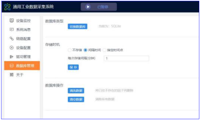
The database management page is shown below:
 】
】
From this page, you can:
-
Select the database type, Currently available SQLite , MySQL and SQL Server .
-
The storage time can be a few minutes interval, or a specified time point.
-
Clean the data and delete the factor columns that no longer exist.
-
Clear data. Generally, clear all data after the device configuration is completed.
********Software Usage
********Start and stop collection
The data acquisition system can start collecting data after the computer is turned on, and no additional operations are required for normal daily use. In some cases, such as equipment maintenance or configuration modification, you can temporarily stop the collection. Click the Pause / Launch the Run button to do this:
It should also be noted that after each configuration change , you need to restart the collection for it to take effect.
********View device collection status
If you need to view the current collection status, you can open the device monitoring page, as shown below:
From this page, you can:
-
View the real-time status of the device.
-
View the real-time value of each factor, as well as the current data time .
-
Enable or disable a device.
-
Counter-control device, modify factor value.
****View system messages
If you need to view the specific communication messages between the data acquisition system and the device, you can open the system message page, as shown in the following figure:
On this page, you can view There are three types of messages:
-
System message: Message generated by system operation.
-
Collection message: byte stream message generated during the collection process.
-
Counter-control message: byte stream message generated during the counter-control process.
****Appendix Expression support operations
The supported operations in expressions include:
| Operation Grouping | Operation | Example |
|---|---|---|
| Basic operations | add | 1+2 |
| reduce | 4-8 | |
| take | 9 * 20 |
| Operation Grouping | Operation | Example |
|---|---|---|
| remove | 6/4 | |
| power | 6^3 | |
| Find the remainder | 10%3 | |
| Scientific Notation | 3.45e5 | |
| Square root | sqrt (4) | |
| Natural logarithm | ln (5) | |
| Common logarithm | lg (7) | |
| Trigonometric operations | Sine | sin (3) |
| Inverse sine | asin (4) | |
| Cosine | cos (5) | |
| Arc Cosine | acos (4.3) |
| Operation Grouping | Operation | Example |
|---|---|---|
| Tangent | tan (7.3) | |
| Inverse tangent | atan (3) | |
| Logical operations | and | 1&&0 |
| or | 1 | |
| No | ! TRUE | |
| Comparison operations | equal | 3==4 |
| Not equal to | 3!=4 | |
| Less than | 3<4 | |
| Less than or equal to | 3<=4 | |
| Greater than | 3>4 |
| Operation Grouping | Operation | Example |
|---|---|---|
| Greater than or equal to | 3>=4 | |
| Bitwise Operations | Position and | 75&39 |
| bit or | 12 | |
| Bitwise XOR | 43432^ | |
| Bit reverse | 43432 | |
| Bit Shift Left | 123<<4 | |
| Bit shift right | 43432>>2 | |
| Statistical operations | Minimum | min (1,2,3) |
| Maximum | max (1,2,3) | |
| average value | avg (1,2,3) |
| Operation Grouping | Operation | Example |
|---|---|---|
| Cumulative value | sum (1,2,3) |
FAQ
1. What is the main function of this edge computing gateway?
It collects, processes, and manages industrial data while enabling communication between field devices and cloud platforms.
2. Does it support multiple protocols?
Yes, it supports Modbus, MQTT, OPC UA, TCP/IP, and optional CAN protocol.
3. What is edge computing used for?
Edge computing allows data processing locally, reducing latency and improving real-time decision-making.
4. Can it integrate with SCADA or cloud systems?
Yes, it fully supports SCADA, MES, ERP, and IoT cloud platforms.
5. Is remote management available?
Yes, the device supports remote configuration, monitoring, and OTA updates.
6. Is it suitable for harsh environments?
Yes, it is designed for industrial-grade environments with 24/7 stable operation.