Multi-Circuit AC Wireless Voltage & Current Sensor / Energy Monitoring Meter
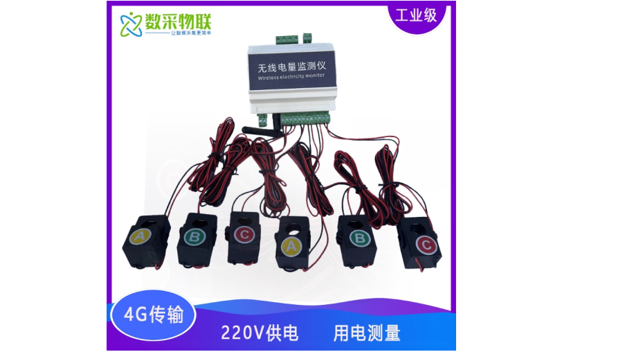
The multi-circuit AC wireless voltage & current sensor / energy acquisition monitor works with multiple split-core transformers to monitor and acquire three-phase voltage, current, power and energy information, and can be used for…
Get a QuoteProduct Details
1 Product Overview
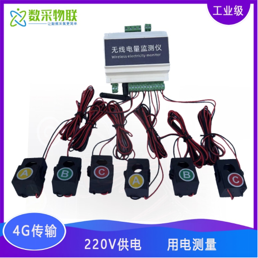
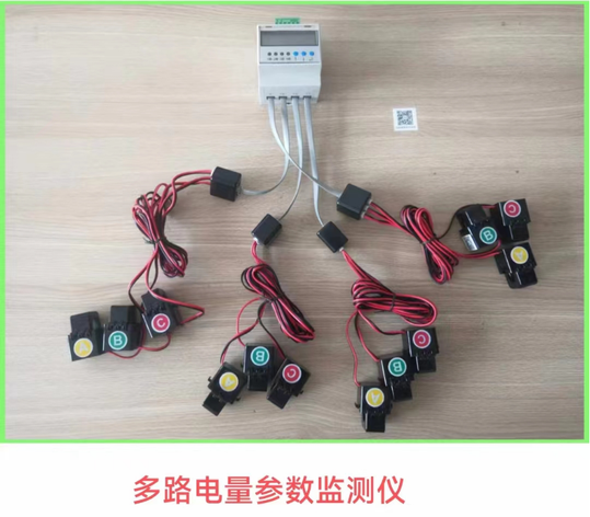
The multi-circuit AC wireless voltage & current sensor / energy acquisition monitor works with multiple split-core transformers to monitor and acquire three-phase voltage, current, power and energy information, and can be used for energy consumption monitoring. It supports RS485 and 4G network interfaces, and data can be integrated with a third-party cloud platform specified by the customer. This product can realize single-phase/three-phase power consumption information monitoring. Equipped with a 4G network interface, it can connect directly to the IoT, letting users view power consumption information on mobile WeChat or a website. It is suitable for scenarios requiring online remote monitoring of power consumption information, and is easy to install with an elegant appearance.
3 Product Features & Parameters
3.1 Acquisition Characteristics
-
Voltage measurement range: 110 ~ 250VAC
-
Current measurement range: 0~120A (other ranges customizable)
-
Voltage accuracy: ±1V (default)
-
Current accuracy: ±0.1A (default)
-
Power accuracy: ±1W (default)
When wiring the RS485 signal cable, note that the A and B wires must not be reversed, and device addresses on the bus must not conflict.
| No. | Interface definition | Description |
|---|---|---|
| 1 | A, B | RS485 communication interface A and B |
| 2 | UA, N | Phase A voltage detection connected to live and neutral; device power interface |
| 3 | UB | Phase B voltage detection connected to live wire |
| 4 | UC | Phase C voltage detection connected to live wire |
| 5 | I1+, I1- | Current transformer 1 connection |
| 6 | I2+, I2- | Current transformer 2 connection |
| 7 | I3+, I3- | Current transformer 3 connection |
| 8 | I4+, I4- | Current transformer 4 connection |
| 9 | I5+, I5- | Current transformer 5 connection |
| 10 | I6+, I6- | Current transformer 6 connection |
| 11 | K1+, K1- | Spare relay output interface |
3.2 Electrical Characteristics
-
Power supply: 220VAC
-
Device power consumption: <=3W (default)
3.3 Communication Characteristics
- Output signal: RS485 Modbus / 4G network
WiFi/LoRa and other communication modes can be customized
3.4 Structural Characteristics
- Overall main unit dimensions: 110×115×60mm
3.5 Storage Environment
- Temperature -40℃ ~ 80℃
4 Core Advantages
-
Simple installation and rapid deployment, helping IoT projects go live quickly
-
Supports custom registration and heartbeat packets, making it easy for the platform to distinguish devices
-
Supports any IoT cloud platform and configuration software, with data protocol integration
-
Supports mainstream cloud platforms such as Alibaba Cloud, Baidu Tiangong, OneNet and Tencent Cloud
-
Supports external connection of multiple sensors
-
Non-invasive acquisition, without affecting the normal operation of equipment
-
Supports remote parameter configuration and FOTA remote upgrade, minimizing on-site installation and maintenance labor costs
5 Communication Protocol
Data upload supports mainstream communication modes such as RS485, TCP, UDP, HTTP and MQTT. The data format can be integrated with third-party platforms in Modbus or JSON form.
5.1 Data Reporting Protocol Parsing Description
Example JSON data message parsing:
{
“fac5”:1, // power factor 5
“current3”:0.04, // current 3, A
“fac4”:1, // power factor 4
“power2”:0, // power 2, W
“energy6”:0, // energy 6, kWh
“current2”:0, // current 2, A
“fac6”:1, // power factor 6
“power5”:0, // power 5, W
“energy5”:0, // energy 5, kWh
“fac3”:1, // power factor 3
“volA”:223.9, // phase A voltage, V
“power6”:0, // power 6, W
“power3”:0, // power 3, W
“current4”:0, // current 4, A
“power4”:0, // power 4, W
“id”:“861658062222974”, // device ID
“volC”:0.2, // phase C voltage, V
“fac2”:1, // power factor 2
“energy4”:0, // energy 4, kWh
“volB”:0.1, // phase B voltage, V
“fac1”:1, // power factor 1
“current6”:0, // current 6, A
“energy1”:0, // energy 1, kWh
“power1”:0, // power 1, W
“energy2”:0, // energy 2, kWh
“current5”:0, // current 5, A
“current1”:0 // current 1, A
}
6 Applications
It can be used for power monitoring needs in various places: distribution cabinets, secondary boxes, terminal distribution boxes, etc. For example: low-voltage distribution in transformer and distribution rooms, outgoing circuits, residential buildings or communities, smart parks, industrial parks, agricultural science & technology greenhouses requiring intelligent power control, hotels, tourist areas and other distribution areas, shopping malls, factories, banks, office buildings and other comprehensive building complexes, hospitals, schools and other densely populated places, museums, cultural centers and other national-level cultural relics protection units, brick-and-wood or wooden structures, and other locations where power cables or equipment with high fire risk require monitoring nodes.
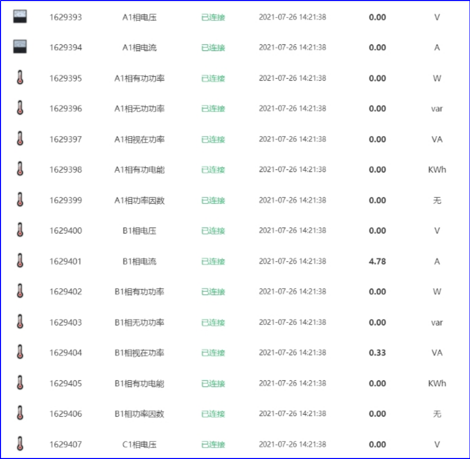
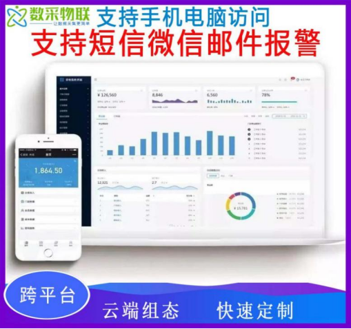
Example of platform web-side data display
7 Installation Notes
Please disconnect the power supply when wiring the product! Please have a professional electrician perform the wiring to prevent short circuits.