Passive Wireless Current Sensor (Three-Circuit)
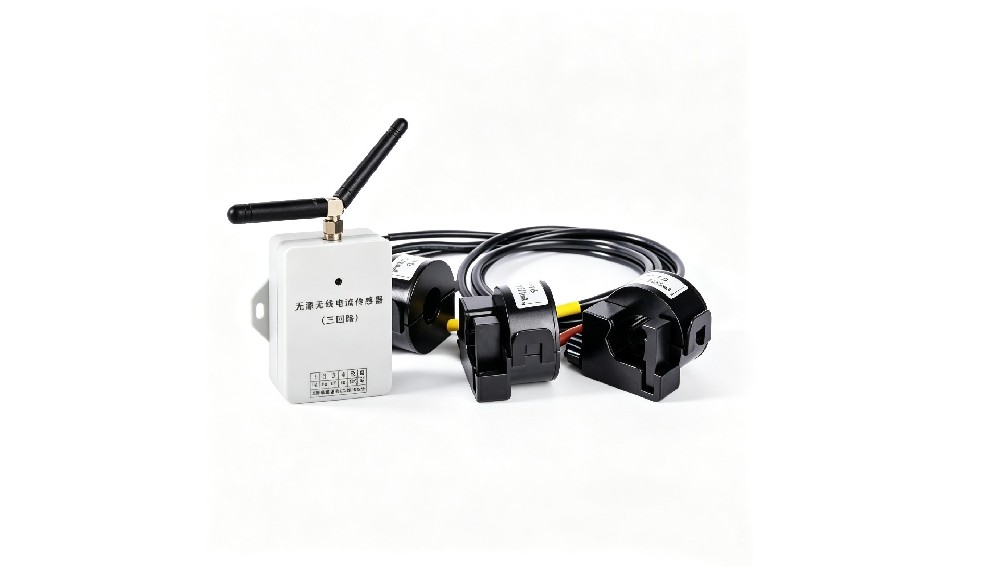
SC-LP-3CTLoRa is a passive wireless current sensor integrating high-precision current measurement and temperature monitoring. It transmits data to a receiving device via wireless communication, enabling real-time remote monitoring…
Get a QuoteProduct Details
1 Product Overview
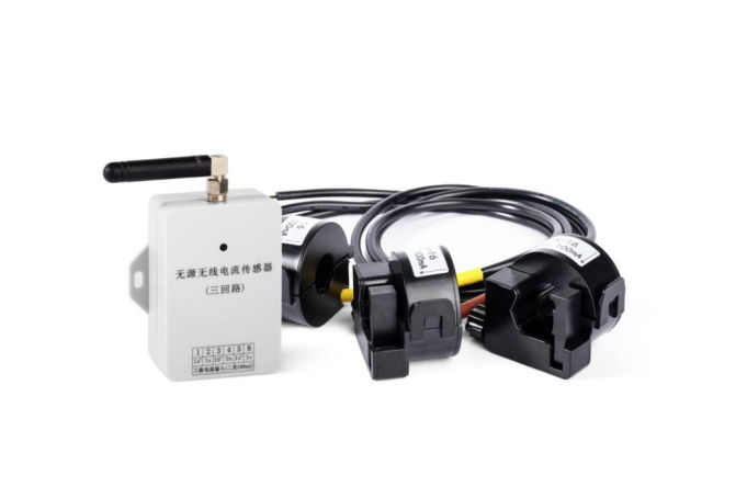
SC-LP-3CTLoRa is a passive wireless current sensor integrating high-precision current measurement and temperature monitoring. It transmits data to a receiving device via wireless communication, enabling real-time remote monitoring of the measured circuit’s data and early detection of potential safety hazards to ensure electrical safety.
The sensor adopts a dual power supply mode: it can operate by connecting to a CT current signal or via an internal battery, switching adaptively and flexibly. No external power supply is required, reducing maintenance. Its compact shape makes installation convenient and adaptable to various application scenarios.
3 Technical Parameters
| Function | Technical parameter |
|---|---|
| Current measurement | Measuring circuits: three; measurement range: secondary input signal 100mA (1.2× overload continuous); measurement accuracy: ≤1% FS; current ratio: settable 1~9999 (set at factory per note) |
| Temperature measurement | One built-in ambient temperature channel; measurement range: -20~85℃; measurement accuracy: ±2℃; resolution: 0.1℃ |
| Wireless transmission | Antenna: external (default angled rod antenna, optional suction-cup antenna); frequency band: 433MHz; transmission distance: 150m (open area); sending period: CT current 20s, battery 5min |
| Power supply | CT current, built-in lithium battery (life 3~5 years) |
| Operating environment | Temperature: -20~85℃; humidity: 5%~95% RH non-condensing |
| Protection rating | IP42 |
| Insulation | Insulation resistance: terminal to housing >500MΩ |
| Installation | Strong magnetic attachment, screw fixing |
4 Wiring Terminals
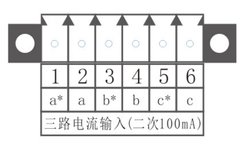
Note: the terminals marked ”*” are the CT secondary current inputs, with input 100mA.
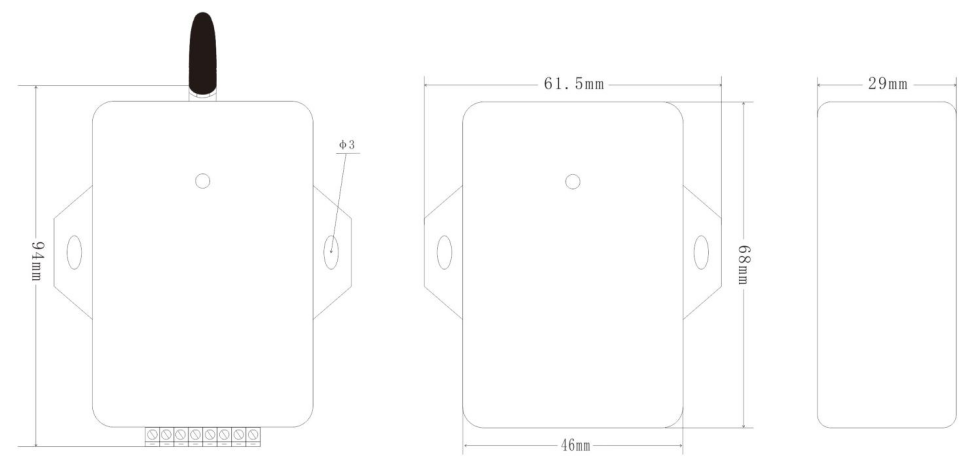
5 Structure & Outline Dimensions
5.1 Current Sensor
| Item | Detail |
|---|---|
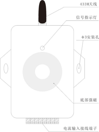
| Sensor structure | See diagram |
| Installation | Bottom strong magnetic attachment or screw fixing |
| Item | Detail |
|---|---|
| Sensor main unit outline dimensions, tolerance ±0.5mm | See diagram |
5.2 Current Transformer (optional)
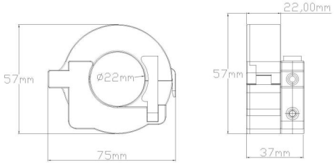
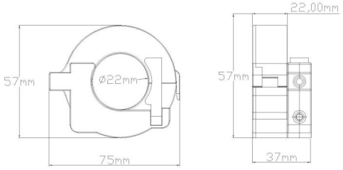
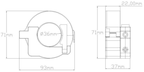
| Performance parameter | CTK-16 | CTK-22 | CTK-36 |
|---|---|---|---|
| Style | Open/close type | Open/close type | Open/close type |
| Rated input current | 100A / 100mA | 200A / 100mA | 600A / 100mA |
| Accuracy | 0.5% | 0.5% | 0.5% |
| In-hole accuracy variation | ≤0.2% (accuracy difference of a 10mm-diameter input current wire at different positions in the through-hole) | ≤0.2% | ≤0.2% |
| Aperture | Φ16±1mm, suitable for cables 5mm-14mm in diameter | Φ22±1mm, suitable for cables 5mm-20mm in diameter | Φ36±1mm, suitable for cables 15mm-35mm in diameter |
| Transformer cable length | 0.5m | 0.5m | 0.5m |
6 Wireless Receiving Devices
It is compatible with multiple series of wireless receiving devices supporting various communication protocols, adapting to various on-site application needs and flexibly integrating into various systems to acquire data.
| Item | Model 1 | Model 2 | Model 3 | Model 4 |
|---|---|---|---|---|
| Outline dimensions | 885937mm | 906525mm | 15013060mm | 18812238mm |
| Display | None | None | 4.3-inch color screen | 7-inch touch screen |
| Number of sensors connected | 64 | 64 | 128 | 128 |
| Power supply | AC/DC220V; DC9-36V | DC9-36V | AC/DC220V | DC9-36V |
| RS485 interface | 1 channel | 2 channels | 2 channels | 2 channels |
| RJ45 | / | Yes | Yes | Yes |
| 4G | / | Yes | Yes | Yes |
| Communication protocol | Modbus-RTU | Modbus-RTU | Modbus-RTU | Modbus-RTU |
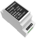
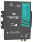
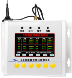
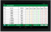
Note: for detailed information on the wireless receiving devices, refer to the manual of the corresponding model.
7 Common Troubleshooting
| Fault symptom | Analysis | Solution |
|---|---|---|
| Indicator light does not flash | Insufficient battery power | Check whether the built-in battery has power; if not, replace it. When powered by battery only, it takes about 5 minutes for the indicator to flash. |
| Inaccurate current measurement | Signal input terminal not tightened | Re-tighten the wiring terminal |
| Transformer failure | Check whether the input signal is consistent with the actual value and whether the transformer cable is open-circuited or damaged; replace the transformer if necessary | |
| Sensor failure | Replace the sensor | |
| No data from the receiving device | Incorrect setting | Check whether the sensor ID and other information set on the receiving device are correct |
| Antenna not properly installed | Check whether the antenna is correctly installed and intact | |
| Distance too far | Verify whether the distance between the sensor and the receiving device is within the nominal range |