Power Marketing Mobile Phone Back-Clip Meter Reader
The Power Marketing mobile phone back-clip (meter reading manager) is a handheld intelligent device with an embedded security unit. It is fully featured and easy to operate, and can be used with Android devices. The product offers…
Get a QuoteProduct Details
1 Product Brief
The Power Marketing mobile phone back-clip (meter reading manager) is a handheld intelligent device with an embedded security unit. It is fully featured and easy to operate, and can be used with Android devices. The product offers 5G/4G, WiFi, Bluetooth, 1D/2D barcode scanning, modulated infrared, laser infrared, high-frequency RFID, RS485/RS232, power bank and mobile hard disk functions. It also has a built-in hardware security encryption unit and Bluetooth communication software encryption using national cryptographic algorithms, ensuring safe and reliable information transmission. Combining ergonomics and innovative design with a color LCD display, it provides a good customer experience and meets the needs of different application scenarios across multiple industries.
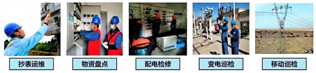
2 Application Scenarios
3 Product Selection
| Product model | Product communication | Differences |
|---|---|---|
| DAQ-BT-BS | Bluetooth 4.0; infrared (DLT 645, 698); RS485, RS232 | 1. Barcode scanning, supporting international 1D and 2D codes. Supports the SM7 national cryptographic algorithm. RFID supports ISO/IEC 14443A |
| DAQ-4G-BS | 4G/WiFi/Bluetooth 5.2; infrared (DLT 645, 698); RS485, RS232 | 1. Power bank. 2. Mobile hard disk. 3. TF and SIM card slots. 4. NFC. 5. Modulated infrared supporting baud rates 1200 and 2400 |
4 Product Appearance
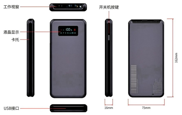
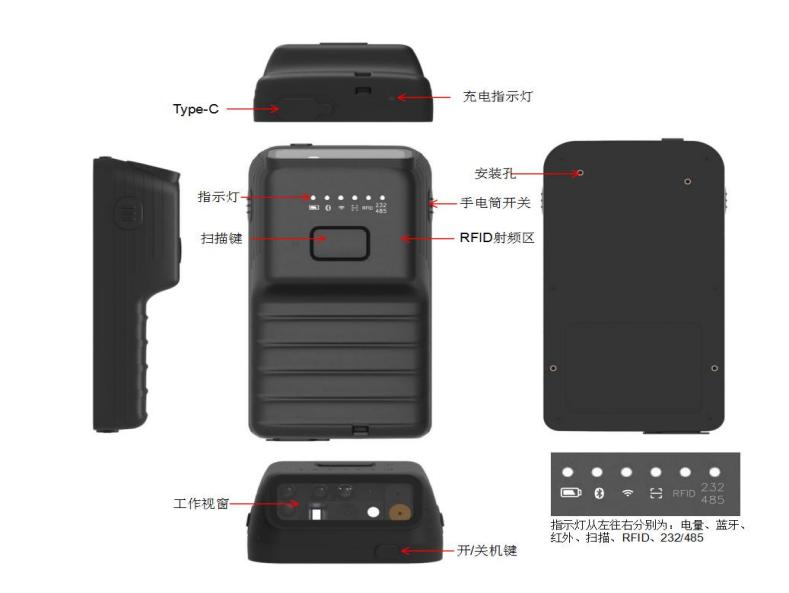
DAQ-4G-BS:
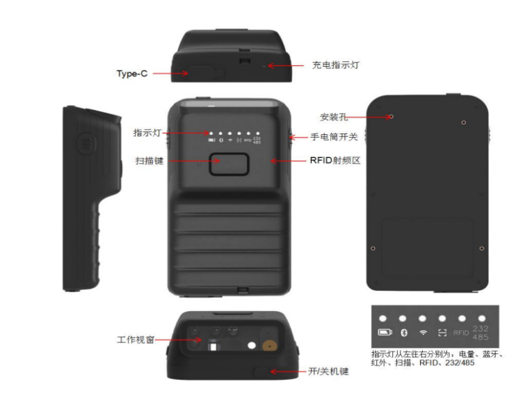
DAQ-BT-BS
6 Product Parameters
| Specification | Details |
|---|---|
| Outline dimensions | 162mm × 75mm × 16mm |
| Battery capacity | 10000mAh |
| Communication - Bluetooth | Supports Bluetooth 5.2, backward compatible with Bluetooth 4.2 |
| Communication - TYPE-C | Supports RS485, supports forward/reverse charging |
| Communication - 5G/4G full network | Supports 5G/4G full network |
| Communication - WiFi | 2.4G/5G dual-band, supports IEEE802.11a/b/g/n/ac |
| Card slot - TF card | Supports 1× TF card |
| Card slot - SIM card | Supports 1× SIM card |
| Laser infrared - emission wavelength | 980±15nm |
| Laser infrared - reading distance | Greater than 3 m |
| Laser infrared - output power | Not more than 7mW |
| Modulated infrared - transmit/receive frequency | 38kHz |
| Modulated infrared - transmit/receive wavelength | Emission wavelength: 940nm; reception wavelength: 900nm~1000nm |
| Modulated infrared - transmit/receive angle | Transmit angle ±45°; receive angle ±45° |
| Modulated infrared - reception distance | ≥5m |
| Modulated infrared - transmission baud rate | Supports 1200 and 2400 |
| RFID/NFC - communication protocol | Supports ISO/IEC 14443A, 15693 |
| RFID/NFC - frequency | 13.56MHz |
| RFID/NFC - operating distance | 3—5cm |
| Interface - power | Input: supports 18W fast charging; output: supports 18W reverse charging |
| Interface - port | TYPE-C |
| Endurance - continuous working time | Not less than 18 hours |
| Operating prompts - LCD display | The LCD screen shows the working status of the back-clip |
| Operating prompts - vibration motor | Vibration prompts for device usage status |
| Operating prompts - buzzer | Power-on and connection/communication success prompt tones |
| Security encryption - security unit | Supports the SM7 national cryptographic algorithm and has a built-in State Grid security software encryption algorithm; supports secure Bluetooth connection and transmission between the phone and the back-clip |
| ESD & drop - static | Contact discharge 8kV, air discharge 15kV |
| ESD & drop - drop | 1.2 m, twice on each face |
| Working environment - temperature | Operating temperature: -30℃ ~ +55℃; storage temperature: -40℃ ~ +60℃ |
| Working environment - humidity | Operating humidity below 93%; storage humidity not more than 95% |
| Working environment - atmospheric pressure | 63kPa ~ 106kPa |
7 Status Display Description
7.1 LCD Display Description
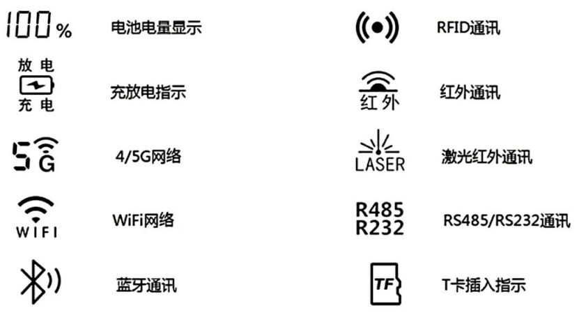
7.2 Battery/Charging Status Display
| Symbol | Working status | LCD icon display |
|---|---|---|
| Charging | Charging (phone back-clip charging) | The “charging” text stays on |
| Charging | Not charging (phone back-clip not charging) | The “charging” text is off |
| Discharging | Discharging (power bank function) | The “discharging” text stays on |
| Discharging | Not discharging (phone back-clip not reverse-charging) | The “discharging” text is off |
| Low battery reminder | Icon flashes | 100% |
| 0%~100% | Displays the current battery percentage on power-on |
8 Function Usage Instructions
8.1 Power On/Off
Long-press the power button for two seconds; the device vibrates and the buzzer sounds to power on. Long-press the power button for two seconds to power off.
8.2 Bluetooth Function
After the phone back-clip is powered on, the Bluetooth icon flashes to enter pairing state. The phone must enable Bluetooth and enter the phone app following the operation instructions; see the app usage section below.
| Symbol | Working status | LCD icon display |
|---|---|---|
| Bluetooth pairing in progress | Bluetooth icon flashes | |
| Bluetooth pairing successful | Bluetooth icon stays on |
8.3 5G/4G Usage
To use the 5G/4G network function, insert a SIM card and enable the SIM card function; see the app usage section below.
| Symbol | Working status | LCD icon display |
|---|---|---|
| 5G | 5G/4G function not enabled (no card detected, no signal) | Icon off |
| 5G | 5G/4G function enabled and network connection successful | Icon on |
| Signal strength | Shows the icon when there is a signal |
8.4 WiFi Function
In the phone app, enter “SIM card parameter settings” to enable the WiFi hotspot.
| Symbol | Working status | LCD icon display |
|---|---|---|
| WiFi not enabled | WiFi icon off | |
| WiFi enabled, no device connected | WiFi icon flashes | |
| WiFi enabled and a device connected | WiFi icon stays on |
8.5 RFID Function
In the phone app, enter “RFID” to enable the RFID/NFC function.
| Symbol | Working status | LCD icon display |
|---|---|---|
| RFID not enabled | RFID icon off | |
| RFID enabled and data is being transmitted | RFID icon flashes |
8.6 Infrared Function
In the phone app, enter “far infrared meter reading” to enable infrared communication and perform actual meter reading.
| Symbol | Working status | LCD icon display |
|---|---|---|
| Infrared communication not enabled | Infrared icon off | |
| Infrared communication enabled and data is being transmitted | Infrared icon flashes |
8.7 Laser Infrared Function
In the phone app, enter “laser infrared meter reading” to enable laser infrared communication and perform actual meter reading.
| Symbol | Working status | LCD icon display |
|---|---|---|
| LASER | Laser infrared communication not enabled | Laser infrared icon off |
| Laser infrared communication enabled and data is being transmitted | Laser infrared icon flashes |
8.9 RS485/RS232 Function
In the phone app, enter “RS485 meter reading” to enable RS485/232 communication and perform actual meter reading.
| Symbol | Working status | LCD icon display |
|---|---|---|
| RS485/RS232 | RS485/232 communication not enabled | RS485/232 icon off |
| RS485/232 communication enabled and data is being transmitted | RS485/232 icon flashes |
8.10 TF Card Function
Insert a TF card and the icon stays on; remove the TF card and the icon disappears.
| Symbol | Working status | LCD icon display |
|---|---|---|
| TF | No TF card detected | Off |
| TF card recognized | On |
8.11 Scanning Function
In the phone app, enter “scan” to enable the scanning function and start scanning directly; 2D codes/barcodes are supported.
8.12 Fault & Warning Description
| Symbol | Working status | LCD icon display |
|---|---|---|
| Phone back-clip working normally | Icon off | |
| Abnormal condition (security unit fault or key not installed) | Icon on | |
| Abnormal condition (back-clip battery over-temperature) | Icon on | |
| Abnormal condition (back-clip charging over-voltage) | Icon on |
8.13 Mobile Hard Disk & Power Bank Function
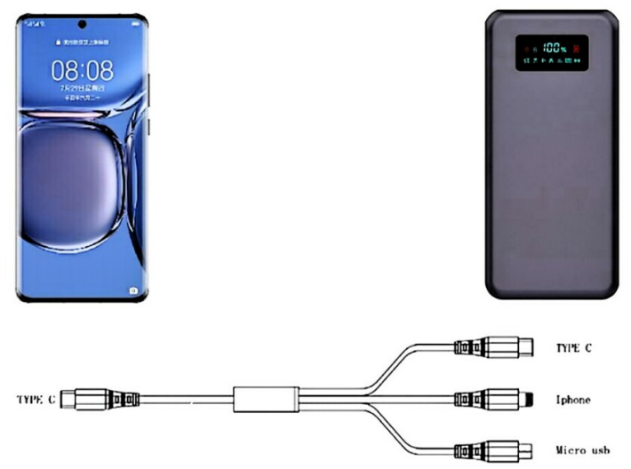
Mobile hard disk function: use the supplied 3-in-1 data cable; insert the main (single) Type-C connector into the phone and connect the other Type-C connector to the back-clip. The back-clip then acts as a mobile hard disk and the phone reads data from it.
Power bank function: use the supplied 3-in-1 data cable; insert the main (single) Type-C connector into the back-clip and connect the other end to the phone (only one phone). The back-clip then acts as a power bank to charge the phone.
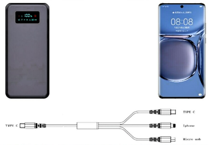
Note: the supplied 3-in-1 data cable can only be used for charging or data transfer between the phone and the back-clip; never use this cable to connect to a charging head.
9 Test App Usage Instructions
9.1 First Launch
Copy or download the back-clip apk file to the phone, open the phone file manager, and tap the apk file to install. After installation, find the back-clip program on the phone and tap to launch it. The program icon is shown below:
9.2 Pairing & Connection
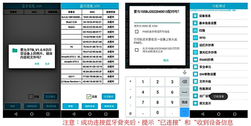
On first launch the program requires permissions to be granted; set them to “allow”. Select the back-clip Bluetooth MAC address and tap the State Grid connection. A prompt to enter the PIN code will appear; after entering the PIN code, tap “OK” to complete pairing and connection with the back-clip. After success, the function test interface appears.
9.3 Device Information & Device Status Query
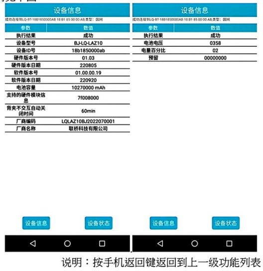
Tap the “Device Information” item in the function list to query device information and device status.
Tap the “Device Information” button to query the back-clip version, company name, model and other information; tap the “Device Status” button to query the back-clip battery voltage, battery level and other information. See the figure below:
9.4 Basic Information Settings
This function allows users to customize the back-clip interaction time — the time after which the back-clip automatically powers off when it has not communicated with the phone.
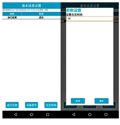
Note: enter the corresponding value and tap confirm; the execution result is returned automatically after a successful setting.
9.5 Scanning Function
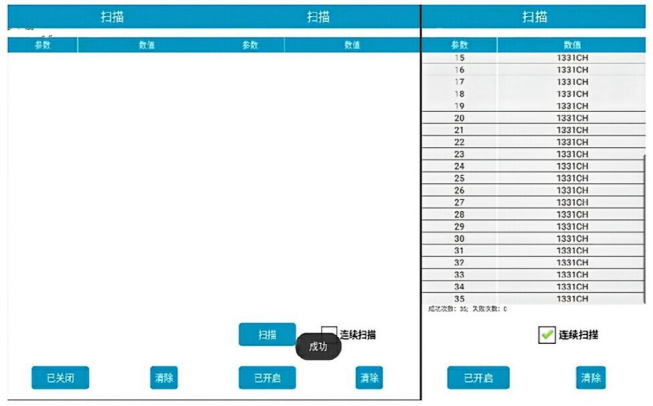
This function is used to scan information. Enter the interface and tap the “Closed” button in the lower-left corner to turn on the back-clip scanning module. After “Success” is prompted, the “Scan” button and the “Continuous scan” radio button appear on the interface.
The “Scan” button performs a single scan; “Continuous scan” tests multiple scans until the radio button is deselected. The scan results are displayed in the parameter and value list, as shown below.
9.6 RFID Card Reading Function
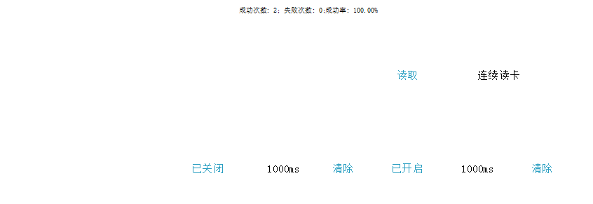
This function is used to read RFID random number information. Enter the interface and tap the “Closed” button in the lower-left corner to turn on the back-clip RFID module. After “Success” is prompted, the “Read” button appears on the interface.
Place the high-frequency RFID card in front of the back-clip and tap the “Read” button to test reading the card number. The read results are displayed in the parameter and value list, as shown below.
| RFID | |
|---|---|
| RFID | Successfully connected to 1058J20220400130018104F0785, type: State Grid |
| Parameter | Value |
| 1 | Read card number: c9aa186a |
| 2 | Read card number: c9aa186a |
9.7 Far Infrared Meter Reading Function
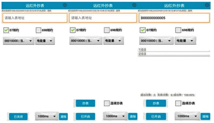
This function is used to read the current data of a meter via far infrared. Enter the interface and tap the “Closed” button in the lower-left corner to turn on the back-clip far infrared module. After “Success” is prompted, the “Read meter” button and the “Continuous scan” radio button appear on the interface.
The “Read meter” button performs a single meter reading; “Continuous meter reading” tests multiple readings until the radio button is deselected. The meter reading results are displayed in the parameter and value list.
Entering this interface defaults to reading with the 07 protocol; select the meter reading data item from the 0000000 drop-down list. To read with the 698 protocol, select the data items in the “698 protocol” drop-down list. The last selected protocol type prevails.
See the figure below:
Note: tap “Continuous meter reading” and then tap “Yes” in the pop-up interface to start the continuous meter reading function. The meter reading results are displayed in the parameter and value list.
9.8 Laser Infrared Meter Reading Test
This function is used to read the current data of a meter via laser infrared. Enter the interface and tap the “Closed” button in the lower-left corner to turn on the back-clip laser infrared module. After “Success” is prompted, the “Read meter” button and the “Continuous scan” radio button appear on the interface. Aim the laser at the meter’s infrared head and tap read meter to start reading the meter data.
Entering this interface defaults to reading with the 07 protocol; select the meter reading data item from the 0000000 drop-down list. To read with the 698 protocol, select the data items in the “698 protocol” drop-down list. The last selected protocol type prevails. See the figure below:
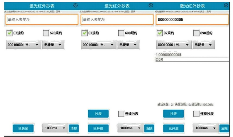
Tap “Continuous meter reading” and then tap “Yes” in the pop-up interface to start the continuous meter reading function. The meter reading results are displayed in the parameter and value list.
9.9 RS485 Meter Reading Function
This function reads the current data of a meter via an RS485 cable. Enter the interface and tap the “Closed” button in the lower-left corner to turn on the back-clip RS485 module. After “Success” is prompted, the “Read meter” button and the “Continuous scan” radio button appear on the interface.
Connect the RS485 cable to the meter and tap read meter to start reading the meter data. The “Read meter” button performs a single reading; “Continuous meter reading” tests multiple readings until the radio button is deselected. The meter reading results are displayed in the parameter and value list.
Entering this interface defaults to reading with the 07 protocol; select the meter reading data item from the 0000000 drop-down list. To read with the 698 protocol, select the data items in the “698 protocol” drop-down list. The last selected protocol type prevails.
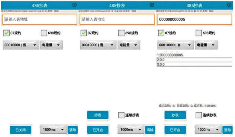
Tap “Continuous meter reading” and then tap “Yes” in the pop-up interface to start the continuous meter reading function. The meter reading results are displayed in the parameter and value list.
9.10 Obtaining Security Unit Information
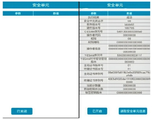
This function is used to read the security unit data information. Enter the interface and tap the “Closed” button in the lower-left corner to turn on the back-clip security module. After “Success” is prompted, “Read security unit information” appears on the interface. See the figure below:
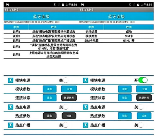
9.11 SIM Card Parameter Settings
Tap “Module power” to display the current SIM card power status; tap “Module power” and then “On” to turn on the module power.
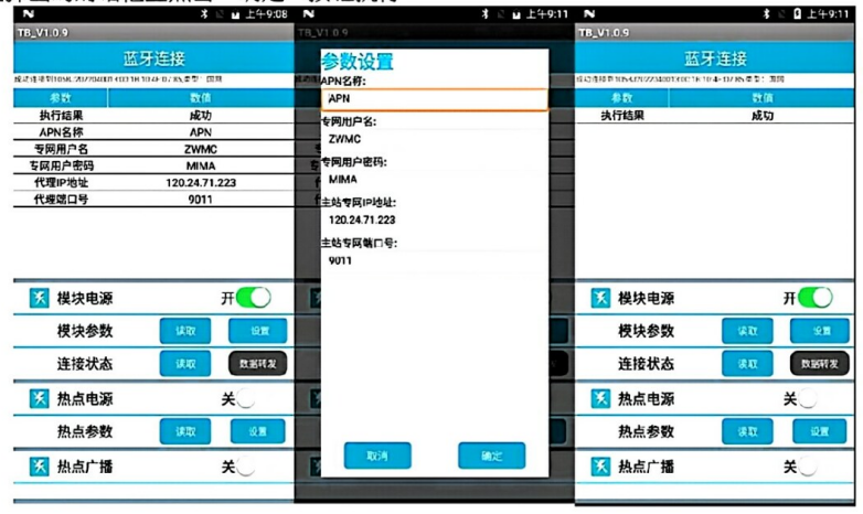
In the module parameter item, tap “Read” to read the module parameters; you can tap the “Set” button to set the module APN name, user name, proxy IP, port and other information. Tap the “OK” button in the pop-up dialog to execute.
In the connection status bar, tap the “Read” button to view the module information. If no SIM card is inserted, the “SIM card flag” displays “Unrecognized SIM card”.
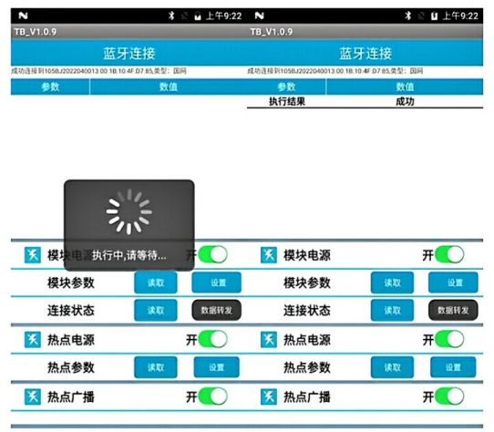
Tap the “Off” button next to hotspot power to turn on the hotspot; tap the “Read” button in the hotspot parameter bar to read the hotspot information; you can tap “Set” to configure the hotspot parameters.
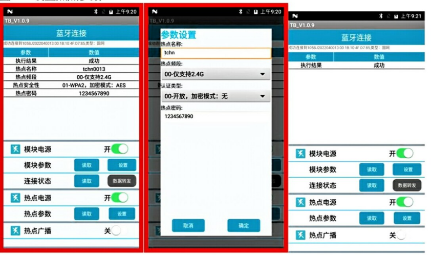
Tap the “Off” button in the hotspot broadcast bar to turn on hotspot broadcast; after it is on, connect to the hotspot to access the internet.
9.12 Back-Clip File Upgrade
This function upgrades the back-clip program. Before upgrading, copy the upgrade file (ending with the rbl extension) to the phone’s sdcard directory.
Step 1: after entering the upgrade interface, tap “Request upgrade”, tap “Select upgrade file” in the pop-up interface, find the file to be upgraded in the phone directory and tap to select it.
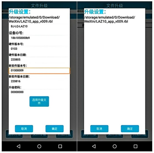
Step 2: tap “File transfer” and tap the “OK” button in the pop-up dialog to execute; after a successful transfer it prompts that the transfer is complete.
Step 3: tap the “Start upgrade” button, enter the upgrade password “00000000” in the pop-up dialog and tap the “OK” button to upgrade.
10 Notes
Do not use chargers and Type-C data cables incompatible with the device, and do not use the supplied dual Type-C cable to connect to a charging head; this may cause charging failure and may lead to fire, explosion or other dangers.
Disconnect the charger from the device when charging is complete or when not charging.
If the charger plug or charger is damaged, do not continue to use it to avoid danger.
Do not perform related operations on the tag while charging.
If the device fails and cannot be used, please contact the manufacturer; do not open the device yourself.